WORMGEAR
Compact · Self-Locking · High Torque
Custom OEM worm gear & worm wheel sets — Module M0.5 to M12, ratio 5:1 to 300:1, tin bronze to stainless steel. Shipped with full CMM and material documentation.
Production
Grade
Module
Certified
Countries
Design
QC Test
Production
Grade
Module
Certified
Countries
Design
QC Test
Worm Gear & Worm Wheel
From plastic self-lubricating miniature gears to heavy-duty carburized alloy steel sets — every product available in custom module, material, and bore configuration. Hover each card for key specifications.


Worm Gear Working Principle & Structure
Understanding the geometry that makes worm drives self-lock, why they need a bronze wheel against hardened steel, and what lead angle determines — helps engineers specify correctly and avoid the most common procurement mistakes.
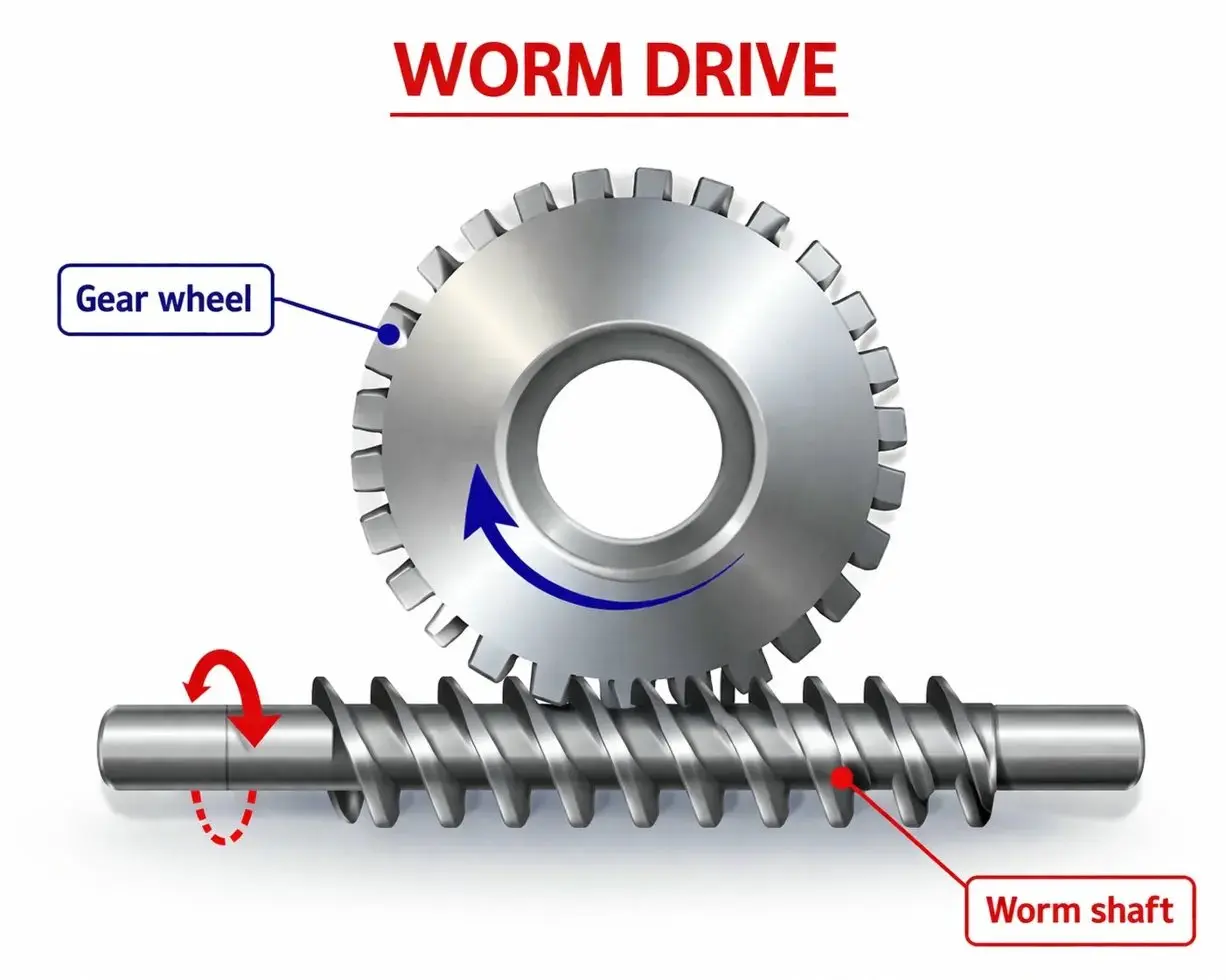
Cylindrical worm gear set — worm shaft (top) engaging worm wheel through sliding helical contact at 90° shaft crossing
How a Worm Gear Drive Works
A worm gear set consists of two components on perpendicular shafts — the worm (a cylindrical shaft with one or more helical threads, resembling a large screw) and the worm wheel (a gear whose teeth are cut with a concave arc across the face width to partially envelop the worm cylinder). Power always flows from the worm to the wheel in standard operation.
The contact between the worm thread and the worm wheel tooth is sliding contact — not the rolling contact of helical or spur gears. The worm thread slides across the wheel tooth face at velocities of 0.5 to 15 m/s. This sliding contact is the source of the worm drive's most useful property — self-locking — and also the source of its efficiency loss and heat generation.
As lead angle λ decreases (higher ratio), efficiency η approaches zero — a mathematical property, not a manufacturing deficiency.
- 90° Shaft Crossing Standard worm gear configuration crosses input and output shafts at exactly 90°. This right-angle layout is architecturally correct for applications where the motor and driven axis must be perpendicular — in a single compact stage.
- High Ratio, Single Stage Adding wheel teeth costs almost nothing in housing volume. A 100:1 worm set is essentially the same physical size as a 20:1 set at the same module. No other gear type achieves this ratio range in one stage.
- Line Contact Geometry When the wheel is hobbed with a worm-profile cutter (matching the worm's own geometry), the contact between worm and wheel becomes a line, not a point — distributing load across 5–10× more tooth face area and multiplying fatigue life.
- Self-Locking Condition Self-locking occurs when lead angle λ is smaller than friction angle ρ'. At ratios above approximately 20:1 with oil lubrication, this condition is reliably met — the wheel cannot back-drive the worm without an external brake.
Worm Shaft
Driving element — always the inputWorm Wheel
Driven element — always the outputContact Mechanics
The parameter that determines service lifeSelf-locking occurs when the worm lead angle (λ) is smaller than the effective friction angle (ρ' = arctan(μ ÷ cos α)). At ratios above approximately 20:1 with standard oil lubrication, single-start worms reliably satisfy this condition — the wheel cannot rotate the worm backward regardless of output torque.
The friction coefficient μ drops as lubricant temperature rises. A drive that reliably self-locks at 20°C with mineral oil may not self-lock at 75°C with fully synthetic oil — the same gearset, different conditions. For safety-critical applications (hoists, solar trackers, medical positioning), self-locking must be verified at maximum operating temperature with the specified lubricant — not assumed from nominal lead angle alone.
A duplex (dual-lead) worm has different lead values on the left and right thread flanks, making tooth thickness increase continuously along the shaft axis. Shifting the worm axially brings a thicker section into mesh, closing backlash without replacing any components. One drive can be readjusted 4–6 times over its service life — multiplying precision longevity versus standard gear set replacement cycles.
Why Engineers Specify Korea Ever-Power
Real engineering advantages — not generic quality claims. Each choice prevents the failure mode that catalog-grade gears cannot avoid.
SCM415 worm shafts carburized to 58–62 HRC then CNC thread ground. Carburizing distorts thread geometry 3–5× the DIN7 limit — grinding corrects this. Non-ground worms cannot hold DIN7 regardless of the datasheet claim.
Every bronze wheel hobbed with a worm-profile hob matched to the specific worm geometry, producing line contact. Line contact distributes load over 5–10× more area than point contact — directly multiplying fatigue life.
Bore diameter, roundness, and concentricity verified on CMM every batch. H7 tolerance = direct shaft mounting without secondary reaming. Bore concentricity within 0.005 mm eliminates periodic angular error.
Every CNC-grade matched pair contact-tested before shipment. Coverage ≥70% of tooth face required. Photograph and percentage ship with every matched pair — quality team can approve without re-testing.
Dual-lead duplex worm shafts restore backlash via axial shift without replacing parts. One drive can be readjusted 4–6 times over its life, multiplying precision service life vs standard replacement cycles.
Material cert, heat treatment record, CMM report, contact pattern photo on request. Medical and defense: ISO 10993, PPAP Level 1–3, MIL traceability available — confirm at order placement.
All OEM designs, CAD files, and sample parts held under NDA. Production tooling dedicated exclusively to your program. NDA signed same day on request — before any file is shared.
M1–M8, SCM415 or tin bronze, standard bore: samples in 15–22 working days from confirmed drawing. Price confirmed within one working day. Sample cost credited to first production order in full.


Manufacturing Capability Range
All parameters are in-house production capability. Custom ranges outside these are discussed on a project basis.
| Parameter | Standard Range | Options / Notes |
|---|---|---|
| Module | M0.5 – M12 | Non-standard modules on request; AGMA diametral pitch series also available |
| Precision Class | DIN5 – DIN9 | DIN6–DIN7 for CNC; DIN8–DIN9 for agricultural/conveyor; DIN5 for CMM |
| Single-Stage Ratio | 5:1 – 300:1 | Start count z1 = 1, 2, 3 or 4; any integer tooth count z2 |
| Bore Tolerance | H7 std; H6 on request | DIN 6885 keyway standard; custom square/hex bore on production orders |
| Worm Shaft Material | C45 / 40Cr / SCM415 / SS304 / SS316 | 42CrMo, 20CrMnTi, 17CrNiMo6 available; GB or JIS equivalent |
| Wheel Material | ZCuSn10Pb1 / ZCuAl10Fe3 / SS316 | Ductile iron, POM, PA66, PEEK also available by specification |
| Backlash (Standard) | 0.04 – 0.15 mm | Per DIN class and module; duplex worm for adjustable near-zero backlash |
| Operating Temp. | −40°C to +120°C | Synthetic PAO lubricant extends upper limit to +140°C continuous |
| Sample Lead Time | 15 – 25 working days | Standard M1–M8; non-standard modules add hob procurement time |
Applications Across Key Industries
Each industry has distinct failure modes. Select your sector to see the specifications that address them directly.

CNC Machine Tools
Fourth-axis rotary tables and indexing heads require angular accuracy that catalog-grade worm gears cannot deliver. A 0.10 mm backlash at 60 mm pitch radius equals 5.7 arc-minutes of dead zone — visible as a dwell mark at every direction reversal.
- DIN6–DIN7 thread ground after carburizing
- Duplex worm sets for near-zero adjustable backlash
- SCM415 worm shaft, ZCuSn10Pb1 tin bronze wheel
- H7 bore — direct shaft mounting, no secondary operations
- Contact pattern ≥70% documented and shipped

Agricultural Machinery
Rice transplanters and rotary tillers fail from three predictable causes: brittle shaft fracture in rocky soil, corrosion during off-season storage, and grease breakdown in summer heat. The correct material specification eliminates all three.
- 40Cr through-hardened shaft — no brittle case-core fracture
- ZCuAl10Fe3 aluminum-iron bronze — 2× tensile strength for stone impact
- Zinc phosphate surface — survives 10-month storage season
- Synthetic Ca-sulfonate NLGI 2 — stable −40°C to +160°C
- PTO bore: Ø25, 30, 32, 35 mm Korean/Japanese standards

Solar Tracking Systems
A tracker drive failing at year 8 of a 25-year project erases the financial case for tracking. Three failure mechanisms — corrosion, grease breakdown, and backlash accumulation — are preventable through correct specification.
- SS316 worm shaft for coastal sites — chloride pitting resistant
- Self-locking verified at site temperature extremes
- Duplex worm — backlash adjustable every 3–5 years without parts replacement
- Synthetic PAO NLGI 2 — stable −40°C to +140°C
- Qualification package: salt spray test + self-locking calculation

Conveyor & Hoist Systems
No other gear type achieves 40:1–100:1 in a single compact right-angle stage with inherent self-locking. Self-locking prevents back-drive when the motor is off — essential for hoist safety without a separate brake.
- Module M4–M12 for heavy loads — up to 5,000 Nm output torque
- Self-locking at ratios above 15:1 — verified for specific conditions
- IP65/IP67 sealed housing configurations available
- DIN8–DIN9 adequate — no unnecessary precision premium paid
- C45 or 40Cr with zinc phosphate for outdoor installations

Medical & Laboratory Devices
Surgical robot joints, patient positioning tables, and infusion pump drives require stainless steel worm gears with documentation meeting medical device quality system requirements.
- SS316 — autoclave compatible (134°C); biocompatibility traceability
- Electropolished flanks Ra ≤ 0.4 µm — ISO Class 5 clean room
- DIN6–DIN7 for surgical robot joint drives
- ISO 13485 traceability documentation package available
- PPAP Level 1–3 for medical device OEM programs

Marine & Offshore Equipment
Chloride-rich marine atmosphere causes through-wall pitting in zinc-plated carbon steel shafts within 3–5 years. SS316's molybdenum content provides genuine pitting resistance for the full expected service life of marine deck equipment.
- SS316 worm shaft — 500-hour salt spray tested on delivery
- Aluminum-iron bronze wheel — resistant to seawater fouling
- IP67 housing sealing — protection against jet wash and submersion
- Anti-corrosion treatment documented with shipment certificates
- Metric and AGMA modules — matching existing marine specs
Precision Worm Gears
in Catalog
Before Dispatch
Answer three questions for a targeted recommendation and specification starting point.
What Engineers Say After Installation
Real feedback from procurement engineers and technical managers across Korea, Southeast Asia, and Oceania.
Worm Gear Engineering Guides
Practical engineering content covering selection, failure diagnosis, ratio calculation, and industry application guides.
Specify the Right Worm Gear for Your Application
Send module, ratio, output torque, bore configuration, and environment. Our engineering team returns a confirmed specification and price within one working day. NDA available before drawing submission.


