Duplex Worm Gear | Dual-Lead, Continuously Adjustable Backlash

Duplex (dual-lead) worm gear sets with different modules on left and right flanks — tooth thickness increases linearly along the worm length, allowing backlash to be adjusted to near-zero (±0.045 mm) by axial worm shift without changing the contact geometry or reducing load capacity. Assembly requires matching arrow marks on both worm and wheel; a V-groove reference tooth sets the zero-backlash position. Applied in CNC rotary tables, precision milling machines, presses, telescope drives, and CMM positioning axes.
Product Overview
Every standard worm drive accumulates backlash as the tooth faces wear. The worn metal is gone — the center distance cannot be reduced, and the only way to close the gap between the worm thread flank and the wheel tooth face in a standard drive is to replace both the worm and the wheel. This is expensive and time-consuming, but for most industrial drives it is acceptable because the backlash specification is not critical. In precision positioning drives — CNC rotary tables, milling machine feed systems, measuring machine axes — even 0.05 mm of angular backlash is too much. A 0.05 mm backlash at the worm wheel pitch circle of a 100 mm diameter wheel translates to approximately 3.4 arc-minutes of positional error, enough to cause visible surface irregularities on a machined workpiece. Korea Ever-Power Worm Gear Co., Ltd manufactures duplex worm gear sets — also called dual-lead worm gears — that solve this problem by making the worm's tooth thickness vary continuously along its length, so that axial shift of the worm restores the original backlash without replacing any components. This duplex worm gear set is the correct solution wherever bidirectional positioning accuracy must be maintained over the drive's service life.
How the Dual-Lead Principle Works — The Engineering Mechanism
A duplex worm is manufactured with slightly different lead values on the left flank and the right flank of each thread. The difference is small but precisely controlled — typically a few tenths of a millimeter difference in axial pitch between the two flanks. The consequence of this difference is that the tooth thickness — measured at the pitch cylinder — increases continuously from one end of the worm to the other. At the thin end, the worm thread fits loosely in the wheel tooth gap with measurable backlash. At the thick end, the worm thread fits tightly with near-zero backlash. The gap between consecutive threads (the tooth space width) decreases correspondingly — the thread and gap are complementary.
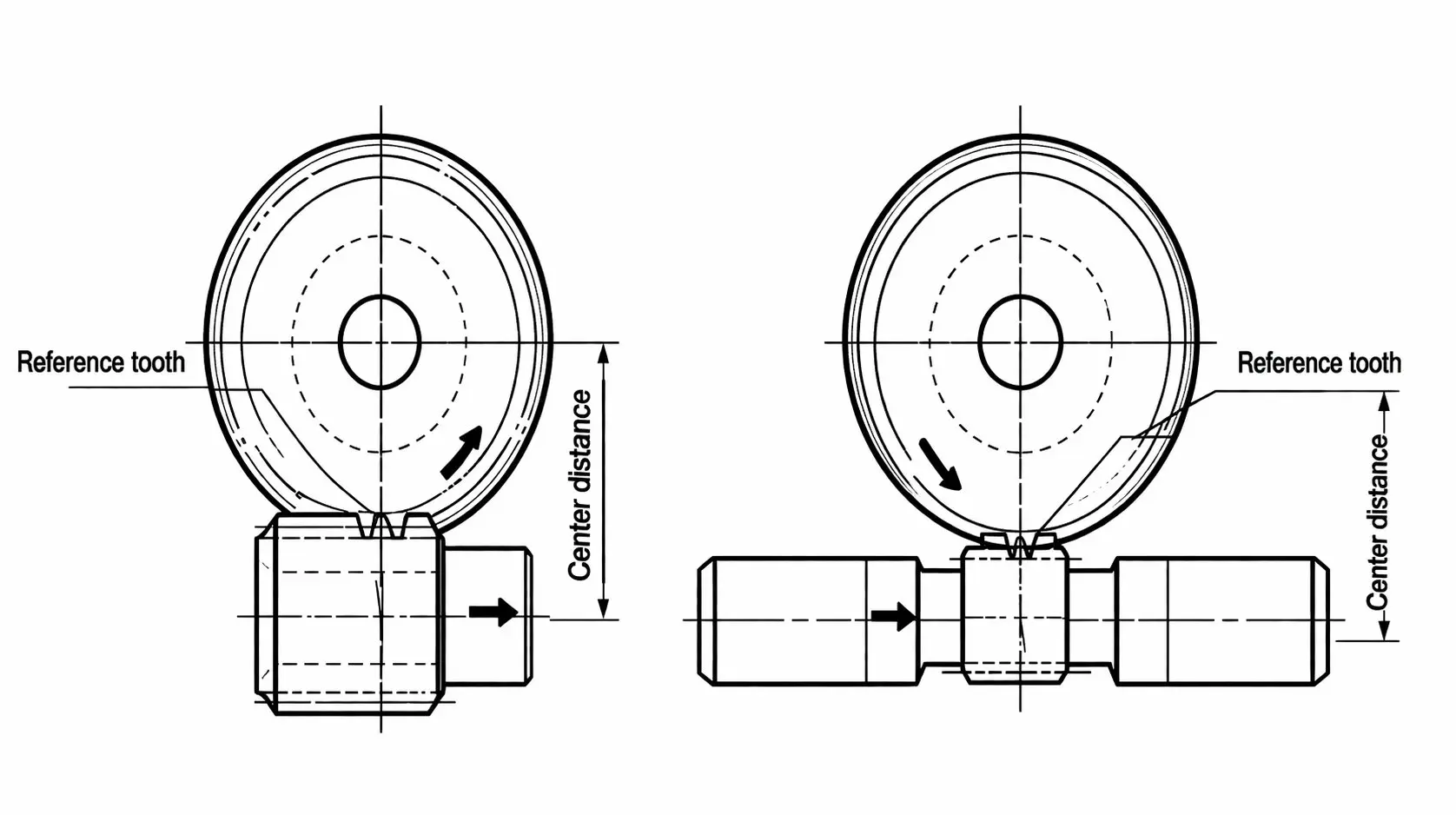
Backlash adjustment is made by shifting the worm axially so that the section of the worm with the needed tooth thickness comes into contact with the wheel, giving the desired backlash (Fig.1). This way, backlash can be adjusted to any desired value when mounting the gear. Even heavily worn gears can be readjusted delicately and continuously without modifying the tooth contact geometry or creating meshing interference — a key advantage over every alternative backlash control method.
At the worm wheel, the different modules on each flank produce different addendum modification coefficients and different rolling circle diameters on the front side versus the rear side of each wheel tooth. Because of this asymmetry, the tooth profiles differ at the front and rear. However — and this is critical to understanding why duplex works — the thickness of each wheel tooth and the tooth gaps remain constant around the wheel circumference. This means the worm can shift to any axial position and the wheel tooth geometry is always correctly matched to the worm at that position. There is no "preferred" axial location with better contact than others — the contact quality is maintained uniformly across the full adjustment range.
Four Alternative Backlash Adjustment Methods — Why Each Falls Short
Before duplex worm gears became widely adopted, engineers used four other methods to control backlash in worm drives. Understanding what is wrong with each of these alternatives clarifies why duplex is the superior solution for precision positioning applications.
| Alternative Method | How It Works | Why It Is Problematic |
|---|---|---|
| Eccentric hub center-distance variation | Both the worm shaft and wheel shaft are mounted in an eccentric hub that rotates to change the center distance | Moving the center distance changes the contact pattern — the worm and wheel were designed for a specific center distance, and deviation shifts the contact zone toward the tooth tip or root, reducing the contact area and increasing tooth stress concentration. Efficiency deteriorates because the oil film geometry at the mesh is disrupted. Each adjustment causes significant start-up wear as the newly positioned contact zone beds in. |
| Conical worm axial shift | The worm is made with a slight taper — larger diameter at one end — and shifted axially to bring a different diameter section into contact with the wheel | A conical worm changes the effective pitch diameter as it shifts, changing the contact normal direction and the pressure angle at the mesh. This means the adjusted drive no longer operates at the design pressure angle — loading on the tooth flanks changes, and in severe cases the tooth geometry may produce edge contact. Manufacturing a correctly tapered worm with the required profile accuracy is also technically demanding. |
| Split worm — two halves (Ott system) | The worm is cut in two halves which are rotated or axially shifted relative to each other, causing the effective thread thickness to increase | Splitting the worm creates a geometric irregularity at the split plane — the thread profiles at the joint are not continuous. This irregularity shows up as a periodic noise event and vibration spike every time the split plane passes through the mesh. Alignment of the two halves at the split is critical and difficult to maintain under operational loads. The risk of improper assembly — one half rotated by an incorrect angle — causing immediate tooth damage is high. |
| Split wheel — two disks | The worm wheel is divided into two coaxial discs which are rotated relative to each other, so that the effective tooth width fills the worm thread gap from both sides simultaneously | Like the split worm, the two-disc wheel introduces load imbalance between the two discs. The disc that takes the driving flank load carries the full torque on first contact; the second disc is loaded only to the extent that its angular displacement precisely matches the first. Manufacturing and setting this angular relationship accurately enough to share load equally is extremely difficult. The assembly is also inherently stiffer in torsion and more susceptible to fretting between the disc interface faces at the contact zone. |
All four methods share the same root problem, stated in the technical literature: adjustments and readjustments interfere with geometrically accurate meshing. They shift the contact profile zone and change its form and size. With this, they decrease the load-carrying capacity and deteriorate efficiency. Each adjustment causes a significant amount of start-up wear. The risk of improper assembly and destruction of the worm gear set is substantial.
Duplex worm gears do not create any of these problems. They always permit geometrically accurate tooth contact and very delicate backlash adjustment. The contact area, load-carrying capacity, and actual efficiency are unaffected by adjustment. In addition, because duplex teeth are executed with an involute tooth form, they are insensitive to modifications of the center distance — for example, caused by worm shaft deflections under load — which is a further reliability advantage in heavily loaded precision drives.
Duplex vs Alternatives — What Changes After Backlash Adjustment
This comparison is the core engineering argument for specifying duplex in precision drives. The "after adjustment" column captures what actually happens to the drive after each backlash readjustment — the information that determines whether the drive will maintain its positioning accuracy specification over repeated adjustments during service life.
| Factor | Duplex Worm (axial shift) | Eccentric Hub (center shift) | Split Worm / Split Wheel |
|---|---|---|---|
| Contact geometry after adjustment | Unchanged — geometrically accurate at all positions | Shifted toward tip or root — contact area reduced | Periodic irregularity at split plane — vibration pulse |
| Load capacity after adjustment | Unaffected — same as before adjustment | Reduced — smaller effective contact area | Reduced — load imbalance between split halves |
| Start-up wear on adjustment | None — smooth repositioning, no new contact zone | Significant — new contact zone must bed in each time | Significant — split-plane irregularity causes wear spike |
| Center distance sensitivity | Insensitive — involute form accommodates center distance variation | Sensitive — must return precisely to design center distance | Sensitive — angular alignment of halves must be precise |
| Adjustment repeatability | Excellent — same axial shift restores same backlash each time | Variable — eccentric position must be set and locked precisely | Poor — half-position alignment is difficult to repeat |
| Assembly risk | Low — clear arrow marks prevent incorrect orientation | Moderate — eccentric lock must be correctly set | High — incorrect half rotation causes immediate tooth damage |
Critical Assembly Instructions — Must Read Before Installation
Duplex worm gears differ in module between the right and left tooth surfaces. This asymmetry means the set has a specific correct orientation — and only one correct orientation. Installing the worm in the wrong direction causes the center distance to be larger than nominal, making assembly difficult and producing incorrect tooth engagement that cannot be corrected by axial adjustment. Please verify both aspects below before assembly.

1. Verifying the Orientation of the Assembly
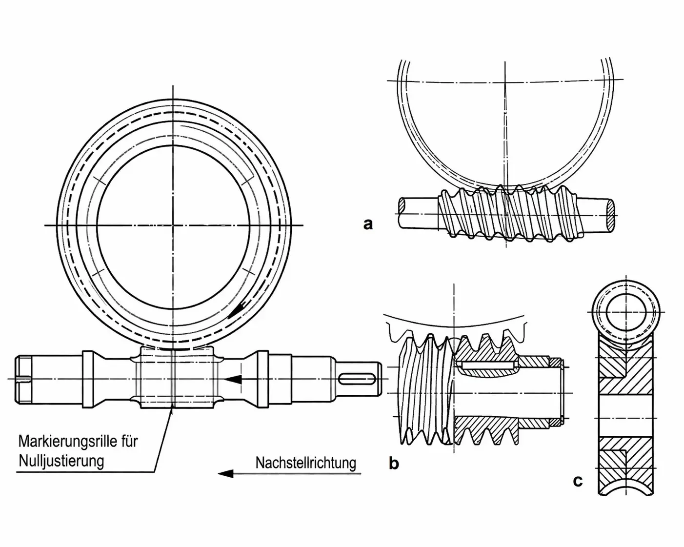
An arrow indicating the correct orientation of assembly is stamped on both the duplex worm and the worm wheel. When assembling, position the worm wheel so that its arrow mark faces toward the front (toward you). Orient the worm so that the direction of its arrow mark coincides with the direction of the wheel's arrow mark — both arrows pointing the same way. Should the assembly be incorrect, the center distance "a" will become greater than the nominal design value, resulting in difficulty completing the assembly and, if forced, improper gear engagement that produces excessive noise, vibration, and accelerated tooth wear from the first revolution.
2. Verifying the Reference Position for Zero Backlash
A V-groove (60°, 0.3 mm deep) machined on the tip peripheral of one specific duplex worm tooth marks the reference tooth. This reference tooth is the tooth at the axial position that produces near-zero backlash (±0.045 mm) when positioned in alignment with the center of rotation of the worm wheel, with the center distance set at the nominal design value "a." The procedure for setting zero backlash is: (1) set the housing center distance to the nominal value "a"; (2) rotate the worm until the V-groove reference tooth is aligned with the wheel's rotation axis; (3) lock the worm housing or bearing adjustment at this position. For applications requiring slightly positive backlash (to accommodate thermal expansion or to prevent tooth binding under load), shift the worm axially toward the thin end by the calculated amount before locking.
⚑ Service Note: As the gear set wears in service and backlash increases, shift the worm axially toward the thick end by the required amount (calculated from the lead difference specification provided with each set). This readjustment restores the original near-zero backlash without dismantling the gearbox — in most designs, the worm shaft axial position is adjustable via a threaded end cap or shim stack. Recalibrate the backlash measurement instrument after each adjustment to confirm the restored value before returning the machine to service.
Applications — Where Backlash Control Is Safety-Critical or Accuracy-Limiting
Duplex worm gears are specified wherever backlash is unwanted or can be harmful: to maintain repeated high-precision positioning in both directions, to prevent impulse-loaded damage when contact flanks alternate, and in drives where positioning error accumulates over time. Typical applications include rotary and tilting tables, milling machines, and presses. The following examples provide the engineering context for each application's specific backlash requirement.
- ▶CNC 4th and 5th axis rotary tables — The angular positioning accuracy of a machining center's rotary table directly determines the dimensional accuracy of machined features on the workpiece. A 0.1 mm backlash at a 150 mm pitch radius translates to 2.3 arc-minutes of position error, which produces a visible step on the machined surface when the table reverses direction for a finish pass. A duplex worm drive adjusted to ±0.045 mm backlash at the worm wheel pitch circle translates to approximately 0.2–0.5 arc-minutes of positional error — below the threshold for visible workpiece defects at standard machining feed rates.
- ▶Precision milling machine table feeds — Table feed drives on bed-type milling machines use worm gears for the cross-feed and longitudinal-feed final reduction. Backlash in the table feed appears as a "dwell" when feed direction reverses — the table does not move for the distance equal to the backlash, then suddenly catches up. This produces a flat spot or step on the machined profile at every direction reversal. Duplex worm drives maintain consistent feed motion in both directions, enabling bidirectional contouring without the feed reversal correction offsets that are required to compensate for backlash in standard worm drives.
- ▶Mechanical presses and forming equipment — Ram position drives on precision stamping and forming presses must return the ram to an exact reference position (typically within ±0.02 mm) for each stroke to maintain consistent part geometry across a production run. Backlash in the drive causes the ram position to be indeterminate at the moment of reversal — the ram may stop at any position within the backlash band. Over a production run of thousands of strokes, this produces dimensional variation that degrades part quality and may cause tooling damage if the ram contacts the die set at an angle.
- ▶Telescope and antenna azimuth/elevation drives — Astronomical telescopes and communications antennas must track a target position continuously while alternating between acceleration and deceleration phases. Backlash causes a "jump" in pointing angle at each reversal — the drive must accelerate through the backlash gap before the load re-engages. This jump is visible as a brief loss of tracking accuracy, measurable on the position encoder. For radio telescopes and high-resolution optical systems, this error directly degrades the signal quality from the tracked source.
- ▶Coordinate measuring machine (CMM) axes — CMM rotary and tilting axes must position a probe tip to within ±1–5 µm of the commanded position. At the worm wheel pitch circle of a typical CMM rotary axis, even ±0.045 mm of worm wheel backlash translates to angular position error. For this reason, CMM rotary axes typically use a preloaded worm drive — the duplex set adjusted past zero backlash into slight preload — to eliminate the backlash dead band entirely. The preloaded condition requires careful adjustment to avoid excess friction, which would degrade positioning repeatability in a different way.

Production Facility
Duplex worm gear manufacturing requires closer dimensional control than standard worm production because the lead difference between flanks must be held to a tighter tolerance — any error in the lead differential directly produces error in the backlash adjustment range. Korea Ever-Power uses dedicated precision NC gear grinding machines for duplex worm thread grinding, with in-process measurement to verify the lead differential at multiple axial positions before the worm is released from the grinding operation.
 |
 |
 |
 |
Related Components

Standard worm and wheel sets for general industrial drives are available alongside duplex configurations for precision applications. Enclosed precision worm gear reducer housings with duplex worm shafts and adjustable worm bearing arrangements, and the full worm drive component catalog, are available from the same manufacturing source. Lead difference specifications and backlash adjustment data sheets are supplied with each duplex set.
Frequently Asked Questions
What exactly happens if the duplex worm is assembled in the wrong orientation (arrows not matching)?
The worm and wheel are designed for a specific relative orientation because the thread is thicker at one end. If the worm is reversed, the thick end of the thread is presented to the tooth gaps that are designed for the thin end — the center distance "a" between shaft axes becomes larger than the nominal design value. In practice, this means the housing either cannot be bolted closed (if the interference is large) or can be closed but produces binding and excessive friction on the first rotation. If forced past this binding, the tooth flanks contact at incorrect positions under high stress, and tooth damage occurs immediately. The arrow marks exist specifically to prevent this error — verifying them takes 30 seconds and prevents immediate gear destruction.
How many times can the drive be readjusted before the worm must be replaced?
In principle, the drive can be readjusted indefinitely as long as the worm tooth faces and wheel tooth faces retain adequate material thickness and surface quality. The worm has a finite useful adjustment range — the distance from the thin end to the thick end — which corresponds to a specific amount of accumulated wear at the wheel tooth face. Once the worm has been shifted to its maximum adjustment position and backlash is still out of specification, the wheel teeth have worn beyond the design limit and the set must be replaced. In practice, for a correctly lubricated drive operating within rated load, a duplex worm set may be readjusted 3–6 times over its service life before replacement, effectively multiplying the service life compared to a standard worm set by a factor of 3–6.
Is a duplex worm set interchangeable with a standard worm set of the same module?
No — a duplex worm cannot be used with a standard worm wheel, and a standard worm cannot be used with a duplex worm wheel. The wheel tooth profiles at the front and rear differ in a duplex set; using the wrong worm produces incorrect contact on one flank and no contact on the other. The center distance, module, and pressure angle are nominally the same between duplex and standard versions, but the worm and wheel must always be used as matched pairs from the same duplex design.
Can the duplex drive be adjusted past zero backlash into preload?
Yes — shifting the worm axially further toward the thick end past the zero-backlash position creates a small amount of preload (negative backlash). Preloaded worm drives eliminate the backlash dead band entirely and are used in CMM rotary axes and high-precision positioning stages. However, preload increases friction at the mesh, which raises power consumption and generates more heat, and significantly accelerates tooth wear because the oil film is thinner under constant compression. For most applications, setting backlash to ±0.045 mm rather than full preload is the better balance between positioning accuracy and service life.
What precision class is available for duplex worm gear sets?
Duplex worm gears are manufactured to DIN precision classes from DIN6 through DIN9. For rotary table and milling machine applications, DIN6 (±8–12 arc-seconds single-tooth pitch error at M5) is the standard specification. For telescope and CMM applications, DIN5 is available on request with extended lead time for the additional grinding and verification operations required. Contact us with your angular positioning accuracy requirement, module, and wheel tooth count — we will recommend the appropriate DIN class and provide a price and lead time for your specific configuration.
Customer Reviews
Kim Hyun-jae — CNC Application Engineer, Seoul Machine Tool Co. (Q4 2025)
We needed zero-backlash worm drive for a precision rotary table upgrade on a five-axis machining center. The duplex set from Korea Ever-Power — DIN6 class M5, Z60, tin bronze wheel — delivered. Angular repeatability measured with a Renishaw AxiSet probe: ±9 arc-seconds bidirectional. After 6 months of continuous bidirectional contouring operation, backlash measured at 0.038 mm — still within the ±0.045 mm specification without any adjustment. Korea Ever-Power supplied the lead difference specification and backlash adjustment procedure with the set, which our application team needed for the machine integration documentation.
Park Jin-woo — Design Engineer, Gyeonggi Precision Equipment (Q1 2026)
We evaluated duplex worm drives against preloaded ball screws for a precision press positioning axis. The duplex worm won on three criteria: load capacity under the eccentric pressing load, self-locking safety when hydraulic pressure drops, and installed cost. Korea Ever-Power's engineering team provided the lead difference spec and a worked example for setting the axial worm position for our specific backlash target of 0.030 mm. Assembly was straightforward — the arrow marks are clearly visible and the V-groove reference tooth is easy to identify. First production batch delivered in 24 days.
Choi Dong-jun — Technical Buyer, Incheon Measurement Systems (Early 2026)
Sourced duplex sets for a coordinate measurement machine rotary axis. Near-zero backlash is critical for our scan path reversal accuracy — we cannot use backlash compensation in the CMM controller because the encoder feedback is too slow to capture the deadband at our probe speed. Korea Ever-Power provided the V-groove reference position data and backlash verification procedure with the shipment. All three sample sets measured at 0.041–0.046 mm backlash at the specified nominal center distance — consistent with the ±0.045 mm specification. Delivery was 23 days from PO confirmation.
Oh Sung-woo — Telescope Drive Engineer, Busan Observatory Equipment (Q3 2025)
We use duplex worm drives for the azimuth axis on research-grade portable telescopes. The key requirement is that the drive must track continuously in one direction for hours without reversal, then slew back and resume tracking — the reversal backlash must not cause the target to jump out of the field of view at the moment of direction change. With the duplex set adjusted to 0.040 mm backlash at our M6 Z80 wheel (pitch radius 240 mm), the angular jump at reversal is 0.57 arc-minutes — below our threshold of 1 arc-minute. Korea Ever-Power was the only supplier who understood the application and could specify the correct lead difference for our module and center distance without requiring an engineering study charge.
Packing & Shipping

Each duplex matched set is individually wrapped in anti-corrosion paper and sealed in a polyethylene bag. The lead difference specification sheet and backlash adjustment data sheet are included with each set. Outer packing in a rigid carton or wooden case depending on quantity. International delivery by DHL, FedEx, TNT, or UPS. Payment: T/T or L/C before shipment.
Additional information
| Editor | Cxm |
|---|
Related products
-

Alloy Steel Worm and Worm Gear for Auto Parts
-

Customized Worm Gear Set | OEM/ODM, Ratio 20:1–300:1, Full Material & Gear Type Coverage
-

Stainless Steel Worm Gear for CNC | ANSI/DIN, Module 1–3, Hardness 55–60 HRC
-

Cylindrical Worm Wheel | Line Contact, High Load Capacity, Bronze & Cast Iron
-

Brass Worm Wheel | M0.5, 20T×1T Matched Set
-

Worm and Wheel | Module M3–M12, Ratio 20:1–300:1, Line Contact Transmission
-

Plastic Worm Gear | POM & Nylon, Module M0.2–M2.0, Self-Lubricating Drive


