Worm and Wheel | Module M3–M12, Ratio 20:1–300:1, Line Contact Transmission

Industrial worm and wheel sets in module M3–M12, DIN6–DIN9 precision. Materials: brass, C45 steel, stainless steel, copper, POM, aluminum, alloy. Single-stage ratio 20:1 standard, up to 300:1 achievable. Tooth face curved for line contact — load capacity 3–5× higher than crossed helical gear point-contact alternatives at the same module. Tolerance 0.001–0.1 mm.
Product Overview
A worm transmission achieves what no other single-stage gear arrangement can: a high reduction ratio — typically 20:1, sometimes exceeding 300:1 — in a 90° shaft layout within a compact housing. The physics that make this possible also create its most important operational property. The worm thread's lead angle is shallow — typically 3° to 11° for ratios above 10:1. When the wheel attempts to drive the worm back, the friction force at the mesh interface (even with oil lubrication) exceeds the tangential force component trying to rotate the worm, and the drive locks in place. This self-locking is not a design add-on; it is a natural consequence of the geometry. Korea Ever-Power Worm Gear Co., Ltd supplies these worm and wheel sets from module M3 to M12 across a full material range for industrial, medical, agricultural, and transport applications.
Product Parameters
| Parameter | Value |
|---|---|
| Model Number | M3, M4, M5, M8, M12 and custom modules |
| Material | Brass, C45 steel, Stainless steel, Copper, POM, Aluminum, Alloy and others |
| Surface Treatment | Zinc plated, Nickel plated, Passivation, Oxidation, Anodization, Geomet, Dacromet, Black Oxide, Phosphatizing, Powder Coating, Electrophoresis |
| Standard | ISO, DIN, ANSI, JIS, BS and Non-standard |
| Precision | DIN6, DIN7, DIN8, DIN9 |
| Teeth Treatment | Hardened, Milled or Ground |
| Tolerance | 0.001 mm – 0.01 mm – 0.1 mm |
| Finish | Shot/sand blast, heat treatment, annealing, tempering, polishing, anodizing, zinc-plated |
| Items Packing | Plastic bag + Cartons or Wooden Packing |
| Payment Terms | T/T, L/C |
| Production Lead Time | 20 business days (sample); 25 days (bulk) |
| Samples | Sample fee $2–$100; freight on buyer's account; fee credited on production order |
| Application | Automatic controlling machines, semiconductor industry, general industry machinery, medical equipment, solar energy equipment, machine tools, parking systems, high-speed rail and aviation transport equipment |
Worm Transmission Engineering — Ratio, Self-Locking, and Efficiency Explained
Worm transmission is composed of a worm (resembling a threaded bolt) and a worm wheel (similar to a helical spur gear), used to transfer motion and power between two staggered shafts. The shaft angle is generally 90°. In standard worm drives, the worm is the driving part. The worm's appearance is similar to a bolt; the worm wheel is similar to a helical spur gear. During work, the worm wheel teeth slide and roll along the spiral surface of the worm. To improve the contact condition, the worm wheel is formed with a circular-arc tooth width so it partially envelops the worm — this creates line contact rather than point contact, and raises the admissible load significantly.
Ratio Calculation — Worked Examples
Gear ratio = wheel tooth count ÷ worm start count. This is straightforward but its implications for ratio range are significant:
| Wheel Teeth (Z) | Worm Starts (n) | Ratio (Z ÷ n) | Output RPM at 1,440 RPM input | Self-locking? |
|---|---|---|---|---|
| 20 | 1 | 20:1 | 72 RPM | Yes (typical) |
| 40 | 1 | 40:1 | 36 RPM | Yes (strong) |
| 40 | 2 | 20:1 | 72 RPM | Marginal (check friction angle) |
| 60 | 1 | 60:1 | 24 RPM | Yes (very strong) |
| 100 | 1 | 100:1 | 14.4 RPM | Yes — also very low efficiency (≈50–60%) |
Self-Locking — When It Works and When It Fails
Self-locking occurs when the worm lead angle (λ) is smaller than the effective friction angle (ρ') at the mesh. The effective friction angle depends on the lubrication condition and the contact surface finish. A well-lubricated mesh with high-additive oil has a lower friction angle than a dry or minimally lubricated mesh — meaning self-locking that is reliable without lubrication may become unreliable with high-quality synthetic gear oil. This is a known and important failure mode in hoists and safety devices that rely on worm drive self-locking. Designers must verify the friction angle under the actual lubrication and temperature conditions of service, not just the dry condition.
For worm drives used in hoists, elevators, or safety-critical holding applications where the load must not fall under any condition, the lead angle should be at least 3–5° below the friction angle at the lowest expected oil viscosity and highest operating temperature. If in doubt, use a single-start worm (higher lead angle provides stronger locking), specify a higher-viscosity oil, or add a secondary mechanical brake.

Efficiency — What the Numbers Mean in Practice
Worm drive efficiency is typically 70–90% for standard single-start configurations, falling to 50–65% at high ratios (60:1 and above). The friction loss generates heat at the mesh zone. This has three practical design implications:
- ◈Motor sizing must account for efficiency loss. A load requiring 500 W at the output shaft requires 500 W ÷ 0.80 = 625 W input at 80% efficiency — 25% more motor power than the output requirement alone suggests.
- ◈Housing surface area must dissipate the heat. For continuous duty at high reduction ratios, thermal analysis of the housing surface area and ambient temperature is necessary. Undersized housings overheat oil, accelerate wear, and reduce service life.
- ◈Oil viscosity grade is critical. At mesh sliding velocities above 10 m/s, low-viscosity (ISO VG 100–150) oil with anti-wear additives is preferred over high-viscosity oil, because the high shear rate at the mesh means thick oil generates more friction heat than thin oil. Below 5 m/s, higher-viscosity oil (ISO VG 220–460) provides better film thickness.
Properly Meshed Conditions
Two geometric conditions must be met for correct worm and wheel engagement. Failing either condition causes uneven tooth loading, rapid wear on one tooth flank, and noise at mesh frequency.
Condition 1 — Module and pressure angle match: The module and pressure angle of the worm and worm wheel in the mid-plane must be equal. Specifically, the worm wheel's transverse module must equal the worm's axial module (both standard values), and the worm wheel's transverse pressure angle must equal the worm's axial pressure angle. If the worm is a DIN standard M4 with 20° pressure angle, the paired wheel must be a DIN M4 at 20° — not M4 at 14.5° or a non-standard pressure angle variation.
Condition 2 — Helical direction and shaft angle: When the shaft stagger angle is 90°, the helical direction (hand of the lead) on both the worm and wheel must be the same — both left-hand or both right-hand. Mismatched hands produce binding at assembly and immediate tooth damage on first operation. Confirm the hand at order placement, especially when mixing parts from different suppliers or production batches.
Why Bronze Wheel + Hardened Steel Worm Is the Standard Material Pairing
The worm and wheel do not perform equally in the sliding contact at the mesh. The worm's thread surface slides across the wheel's tooth face at velocities from 0.5 m/s (slow conveyors) to over 10 m/s (high-speed power transmission). At these velocities, the two materials wear each other differently depending on their hardness differential and tribological compatibility.
The classical pairing — hardened steel worm (55–60 HRC) against cast tin bronze wheel — works because of a specific tribological mechanism: the bronze surface preferentially forms a thin sacrificial transfer layer under the sliding contact pressure. This transfer layer — essentially a smeared bronze film on the steel worm thread — acts as a solid lubricant at the mesh, keeping the friction coefficient low (approximately 0.05–0.10 with oil) and preventing adhesive wear (galling) from occurring between the surfaces. When the bronze layer wears through, fresh bronze from the wheel face replenishes it. This self-renewing mechanism is why bronze worm wheels outlast steel-on-steel or aluminum-on-steel alternatives under continuous sliding.

The worm material options and their characteristics:
- ◈Cast tin bronze (ZCuSn10Pb1): Best friction reduction and anti-galling properties; slightly lower tensile strength (250–280 MPa) than aluminum bronze; forms the best transfer layer; slightly higher cost. Avoid sulfur-containing EP oils — sulfur chemically attacks the tin content.
- ◈Aluminum-iron bronze (ZCuAl10Fe3): Higher tensile strength (550–600 MPa) than tin bronze; better for heavy intermittent loads; somewhat weaker anti-galling behavior under continuous high sliding speed. Compatible with most EP oil formulations.
- ◈Cast iron (grey or ductile): Lowest cost; acceptable friction behavior due to graphite content; requires aging treatment to stabilize dimensions; best choice for slow drives (< 2 m/s) where cost is the primary constraint. Not suitable for high sliding speed or continuous duty.
- ◈Engineering plastics (POM, nylon): Self-lubricating; suited to small modules (< M3) and light loads; incompatible with heavy industrial worm drives but common in instrument and appliance applications at M3 and below.
Features of Worm and Wheel Drive
- ✦Large single-stage ratio: 20:1 to 300:1 in a single stage — far more compact than staggered-shaft helical gear mechanisms at equivalent ratio, which typically require two or three stages.
- ✦Line contact load capacity: The arc-curved tooth width creates line contact rather than point contact — load capacity is 3–5× higher than crossed helical gear sets at the same module.
- ✦Multi-tooth meshing: Several wheel teeth are in simultaneous contact with the worm thread, distributing load and providing smooth, low-noise drive even at high torque.
- ✦Self-locking at low lead angles: When the lead angle is smaller than the equivalent friction angle, the mechanism self-locks — worm can drive wheel, wheel cannot drive worm — enabling reverse self-locking as a safety feature in lifting and heavy machinery.
- ✦90° layout: Right-angle shaft arrangement suits corner drives, machine feed systems, and confined installations where parallel or bevel gears cannot fit.
- Important limitation — efficiency and heat: The large relative sliding velocity at the worm mesh generates more friction heat than any other gear type at equivalent power. Transmission efficiency is typically 70–90%. The axial force on the worm bearing is also large — significantly larger than in spur or helical gear arrangements — and must be accommodated by the worm shaft bearing selection. These two characteristics require specific attention in drive design and are not limitations of any particular supplier's product; they are inherent to the worm transmission principle.
Line Contact vs Point Contact — Technical Comparison
The distinction between a worm-and-wheel set and a worm paired with a helical gear (crossed helical gear set) is often misunderstood in purchasing. Both configurations run on 90° crossed shafts. The critical difference is in the tooth contact geometry, which determines the load capacity ceiling.
In the crossed helical gear set, only theoretical point contact exists between the mating flanks. The actual contact patch is an ellipse of a few square millimeters under load. In a true worm-and-wheel set, the wheel teeth are milled with a hob whose profile matches the worm geometry — the result is a tooth face curved along the width that partially wraps around the worm, creating a contact line that spans a significant fraction of the tooth face width. This difference in contact area determines load capacity.
| Aspect | Worm + Worm Wheel (Line Contact) |
Worm + Helical Gear (Point Contact) |
|---|---|---|
| Contact geometry | Line across tooth face — wheel tooth wraps around worm | Theoretical point — small ellipse under load |
| Load capacity (same module) | 3–5× higher than point contact alternative | Limited — suited only to light loads |
| Wheel tooth form | Arc-curved tooth width — requires worm-profile hob to mill correctly | Standard helical tooth — milled with standard helical hob |
| Manufacturing requirement | Worm-profile hob matched to worm geometry — higher tooling cost, correct tooth form guaranteed | Standard helical hob — lower tooling cost, lower load capacity |
| Lubrication requirement | Essential at medium-to-high loads — oil film between line-contact flanks | Light duty may run with minimal lubrication — but small contact area still wears without oil |
| Ratio range typical | 5:1 to 300:1 in a single stage | 3:1 to 15:1 practical range |
| Recommended application | Power transmission at moderate to high continuous loads | Instrument, light-load motion drives at low ratios |
Five Parameters to Confirm Before Requesting a Quotation
Worm and wheel sets can only be correctly specified when five parameters are fully defined. A quotation without these parameters produces a price that may not match your actual requirement — the most common cause of post-delivery dimensional or performance complaints.
- →Required gear ratio and allowable tolerance. Ratio = wheel tooth count ÷ worm starts. Confirm whether you need an exact ratio (±0 tooth count on the wheel) or whether adjacent ratios (e.g., 19:1 or 21:1 instead of 20:1) are acceptable for your kinematics.
- →Output torque and input speed. Peak torque (Nm), continuous torque (Nm), and input shaft speed (RPM). These three values determine the module size. Undersized module at the specified torque produces premature tooth fatigue. Oversized module adds cost and weight without benefit.
- →Material pairing and operating environment. State the environment — indoor dry, outdoor, washdown, food contact, corrosive atmosphere. This determines whether carbon steel, stainless, bronze, or a special material is needed. If you state only the ratio and torque, we will quote standard material (C45 worm, tin bronze wheel) as default.
- →Precision class. DIN9 for general conveyors, agricultural, and packaging machinery. DIN8 for most industrial drives with moderate positioning requirements. DIN7 for indexing tables and CNC auxiliary axes. DIN6 for high-precision servo drives and instruments. Higher class requires more machining time — confirm the class before pricing, as DIN6 vs DIN9 can differ by 30–60% in unit cost at larger modules.
- →Self-locking requirement and duty cycle. If the drive must hold load without a separate brake, state the load at the wheel shaft and confirm the lead angle against the friction angle at your operating lubrication condition. Also state whether operation is continuous, intermittent (duty cycle % and on/off cycle time), or occasional — this affects heat generation sizing.
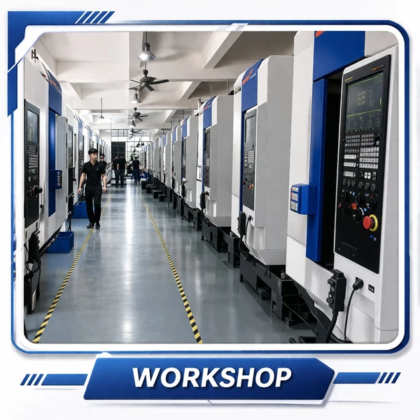
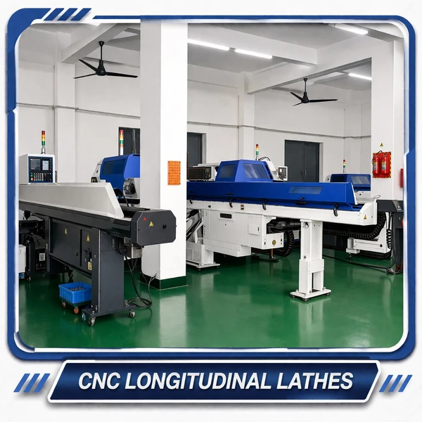
Production Facility
 |
 |
 |
 |
 |
 |
Related Components
A worm and wheel set forms the heart of any worm drive system — the hardened worm shaft engages the wheel at a 90° axis offset, delivering high reduction ratios in a compact footprint with inherent back-drive resistance. For applications requiring a fully enclosed, installation-ready solution, our worm gear reducers house the worm and wheel within a precision-bored casing, providing pre-aligned geometry, integrated sealing, and consistent output torque across the load range.
Worm Shaft — The driving element that mates with the worm wheel. Precision-ground thread profiles ensure correct mesh geometry, efficient load transfer, and extended service life across the full reduction range.
Worm Gear Reducer — A self-contained unit enclosing the worm and wheel within a sealed housing. Ideal when consistent center distances, integrated lubrication, and ready-to-mount convenience are required.

Frequently Asked Questions
Why does the worm wheel need to be made with a specific hob — can I use a standard gear cutter?
A standard involute gear hob would cut straight or helical teeth on the wheel blank. These teeth produce only point contact when meshed with the worm. A worm-profile hob (whose cutting edges match the worm thread geometry) mills the arc-curved tooth face that gives line contact. Cutting the wheel with the wrong hob is a common source of premature wear and noise — visually the gear looks correct but the contact pattern is wrong. All wheel sets from Korea Ever-Power are cut with the correct matched hob for the worm module and thread form.
How do I identify the correct gear if I cannot find the original specifications?
Send us the physical gear. We measure the worn gear on our CMM — tooth profile, module, lead angle, hand of lead, bore diameter, keyway dimensions, and OD. We return a confirmed drawing within 3–5 working days. We specialize in reverse engineering from samples and have rebuilt the specifications for gears from equipment as old as 40 years where no drawing existed. Reverse engineering is included in our standard service at no charge on orders above the minimum sample quantity.
Can I order metric gear sizes that are not standard catalog modules?
Yes. We hold tooling for all standard metric modules and can source custom hobs for non-standard module sizes (for example, M2.25 or M3.5 that appear in some European equipment). Lead time for a non-standard hob procurement adds approximately 10–15 working days to the first order; subsequent orders from the same hob proceed at standard lead time. State the module, tooth count, and wheel face width when requesting a quotation.
How does oil viscosity affect efficiency and self-locking?
Higher-viscosity oil improves film thickness at the mesh, reducing metal-to-metal contact and surface fatigue. However, higher viscosity also increases viscous drag at the mesh, reducing efficiency. At slow worm speeds (< 3 m/s), ISO VG 220–460 is typically correct. At faster speeds (> 5 m/s), ISO VG 100–150 gives better efficiency. As for self-locking: highly refined synthetic oils with low friction coefficients can reduce the effective friction angle below the worm lead angle — meaning a drive that reliably self-locks with mineral oil may not self-lock with a premium synthetic. If your application relies on self-locking as a safety feature, test with the actual lubricant under service temperature conditions.
What is the sample fee and process?
Sample fees range from $2 to $100 per piece depending on module size and material. Freight is on the buyer's account. After the sample is confirmed and a production order placed, the sample fee is credited in full against the first production invoice. For standard module and material combinations, samples are ready in 20 business days. We only accept payment before shipment — T/T and L/C are the standard payment terms.
Can the worm and wheel be supplied with matched material certification?
Yes. Material certificates (mill certificate, chemical composition, mechanical properties) are available for all material grades — particularly for bronze alloys and stainless steel where the specific alloy content affects the lubrication compatibility and corrosion resistance. Certification is standard for orders where it is requested at the time of order placement. Retroactive certification for shipped goods is not possible; state the requirement before production begins.
Customer Reviews
Yoon Seok-min — Plant Engineer, Gyeongnam Packaging Machinery Co. (Early 2026)
M4 tin bronze worm wheels for a wet-environment packaging line with daily CIP washdown cycles. Four months of 16-hour daily operation: zero corrosion visible on the wheel bore or tooth faces, no measurable backlash increase. Efficiency is within 2% of the design value — no unexpected heating of the gearbox housing. Bronze material certification was provided without delay. Price was 22% below our previous European supplier for the same spec on the same DIN8 class.
Kwon Jae-sung — Engineer, Incheon Industrial Hoist Co. (Late 2025)
Self-locking is a safety-critical requirement for our manual chain hoist — if the worm drive does not hold the load when the operator releases the handle, the hoist drops. We verified the lead angle and friction angle calculation with Korea Ever-Power's engineering team before ordering. M8 bronze sets mesh smoothly, hold load without creep in 8 months of daily operation, and passed our internal safety audit with material certificate. This is the first supplier who actually engaged with the self-locking physics question rather than just saying "yes it's self-locking."
Song Hye-jin — Maintenance Manager, Gyeonggi Agricultural Equipment (Q3 2025)
Replaced tin bronze worm wheels on 12 rotary tiller gearboxes. All 12 bores measured within H8 tolerance on incoming inspection — no reaming required, straight to assembly. After a full growing season in wet, muddy field conditions with daily vibration and intermittent shock loads, tooth wear is visually minimal on all units. Unit price was 20% below our previous Taiwanese supplier for equivalent quality.
Lim Sung-ho — Production Buyer, Busan Conveyor Solutions (Q1 2026)
We source M4 and M6 bronze wheel sets quarterly for conveyor drive rebuilds. The consistency is the most important thing for us — not price. Batch-to-batch bore diameter spread has been within ±0.008 mm across six quarters of orders, which allows our rebuild technicians to work without incoming measurement. Lead time has been 22–24 days on every order without exception. No surprises in 18 months of sourcing.
Packing & Shipping

Additional information
| Editor | Cxm |
|---|
Related products
-

Alloy Steel Worm and Worm Gear for Auto Parts
-

Customized Worm Gear Set | OEM/ODM, Ratio 20:1–300:1, Full Material & Gear Type Coverage
-

Stainless Steel Worm Gear for CNC | ANSI/DIN, Module 1–3, Hardness 55–60 HRC
-

Duplex Worm Gear | Dual-Lead, Continuously Adjustable Backlash
-

Cylindrical Worm Wheel | Line Contact, High Load Capacity, Bronze & Cast Iron
-

Brass Worm Wheel | M0.5, 20T×1T Matched Set
-

Plastic Worm Gear | POM & Nylon, Module M0.2–M2.0, Self-Lubricating Drive


