Worm Gear for Solar Tracking Systems — 25-Year Reliability Specification
A tracker drive that fails at year 8 of a 25-year project destroys the financial case for tracking over fixed-tilt. This guide identifies the three mechanical mechanisms that cause solar tracker worm drives to fail before the project lifecycle ends — and what to specify to prevent each one.
The Economics That Make Drive Reliability Non-Negotiable
A single-axis horizontal tracker on a 100 MW utility solar project improves energy yield by approximately 23% over a fixed-tilt array at the same site latitude. On a 100 MW site in South Korea with a capacity factor of 15%, this means roughly 3.45 million additional kWh per year. At a PPA price of 0.09 USD/kWh, that is about 310,000 USD per year in additional revenue — the financial justification for choosing trackers over fixed-tilt in the first place.
Now consider a gearbox replacement event at year 8 on a 1,000-drive site. A field mobilization, equipment rental, and 1,000 replacement drives at 280 USD each costs approximately 560,000 USD in parts and labor. The replacement event also takes the affected tracker rows offline for an estimated 7 days average across the fleet, costing roughly 60,000 USD in lost generation. The total event cost — 620,000 USD — is equivalent to two full years of the yield improvement benefit. The project’s internal rate of return calculation assumed no major drive replacement events over 25 years. One event at year 8 has already consumed 8% of the total lifecycle yield advantage.
This is why the specification of the เฟืองตัวหนอน set in a solar tracker drive is an investment decision, not a purchasing decision. The cheapest gear set that fits the motor adapter and output shaft interface is not the correct answer. The correct answer is the gear set that will still be operating within specification in year 25 — and Korea Ever-Power designs its solar tracker worm gears around that requirement specifically.

Three Mechanisms That Kill Solar Tracker Drives Early
Mechanism 1 — Corrosion of the Worm Shaft in Marine and Industrial Atmospheres
A zinc-plated carbon steel worm shaft in a coastal atmospheric environment undergoes a failure sequence that is well-documented in offshore and coastal industrial installations but often underestimated in solar project specifications. Chloride ions in marine air penetrate zinc plating at coating discontinuities — scratches, thread root stress cracking from thermal cycling, and porosity in the electrodeposited zinc layer. Once chloride reaches the steel substrate, pitting corrosion initiates and progresses at a rate 4 to 8 times faster than the galvanic protection of the residual zinc can suppress. In a moderate coastal Korean environment (3–5 km from the sea), a zinc-plated carbon steel worm shaft can develop through-wall corrosion pits at the thread root within 5 to 7 years. The first visible symptom is usually noisy operation from rough thread engagement; the functional failure is a rapid increase in backlash followed by complete loss of self-locking when the pits create surface stress concentrations that allow thread deformation under wind load.
Mechanism 2 — Grease Thermal Breakdown Under Daily Temperature Cycling
Solar tracker gearbox housings in desert and continental climates undergo daily temperature cycles that mineral grease was not formulated to withstand. A sealed gearbox in direct sun in summer reaches 75–85°C internal temperature by midday — driven by absorbed solar radiation on the housing surface, not just by gear mesh friction. At these temperatures, mineral grease base oil bleeds from the thickener at a measurable rate. The separated oil migrates under gravity to the lowest point of the housing. The gear surfaces above the oil pool gradually run with only the dry thickener residue as lubrication. By the time ambient temperatures drop in autumn and the process reverses, the tooth surfaces have accumulated fatigue damage from the dry-running periods. Over 5 to 8 years of daily thermal cycling, this mechanism produces progressive adhesive wear on the bronze wheel tooth faces. The end state is a drive that has lost 40–60% of its rated torque capacity due to tooth profile degradation.
Mechanism 3 — Backlash Accumulation and Loss of Tracking Accuracy
Backlash in a worm gear set represents the angular dead zone when the axis reverses direction. In a new tracker drive adjusted to 0.05 mm backlash at the worm wheel pitch circle, this dead zone is approximately 0.05 ÷ 60 mm pitch radius = 0.00083 radians = 2.9 arc-minutes. As the tin bronze wheel teeth wear under 9,000 daily tracking cycles over 25 years, backlash increases at an estimated 0.015–0.030 mm per year depending on contact stress level and lubrication condition. By year 6 to 8 of operation with no adjustment, backlash may reach 0.15–0.20 mm — equivalent to 8.6 to 11.5 arc-minutes of tracking dead zone. A panel 0.15 degrees off-track during peak irradiance loses approximately 0.4% of daily yield. Over 10 years of operation at this deviation, the cumulative energy loss can exceed 1.5% of lifetime generation — measurable in the project’s energy performance ratio and potentially triggering performance warranty discussions with the project owner.
Specification Range — Solar Tracker Worm Gear
| พารามิเตอร์ | ช่วงราคา / ตัวเลือก | Solar Application Notes |
|---|---|---|
| โมดูล | M4 – M10 | M5–M8 for most utility single-axis tracker rows |
| อัตราส่วนการลดลง | 40:1 – 150:1 | 60:1 – 100:1 most common for horizontal single-axis trackers |
| วัสดุเพลาหนอน | C45 + zinc phosphate (inland), SS304 (freshwater exposure), SS316 (coastal / marine) | Site-specific material selection — see Site Classification Matrix below |
| วัสดุล้อ | ZCuSn10Pb1 (tin bronze) standard; ZCuAl10Fe3 for high-wind, high-load sites | Tin bronze preferred for continuous tracking duty and anti-scuffing properties |
| คลาสความแม่นยำ | DIN7 – DIN8 | DIN7 where tracking accuracy within ±0.15 degrees is specified |
| Duplex worm option | Available — backlash adjustable without component replacement | Recommended for dual-axis and high-accuracy single-axis installations |
| Self-locking verification | Confirmed at site temperature extremes with synthetic lubricant specified | Documented safety margin vs wind torque provided with each tracker grade set |
| ข้อกำหนดของสารหล่อลื่น | Synthetic PAO NLGI 2, -40°C to +140°C; ISO VG 220–460 for oil-bath housings | No mineral grease — bleed above 75°C leaves tooth surfaces dry at peak generation hours |
| อุณหภูมิในการทำงาน | -40°C to +85°C | Housing surface temperature in direct midsummer sun: up to 85°C in Korean / Southeast Asian climates |
Self-Locking at Temperature Extremes — Why Assumptions Are Dangerous
The self-locking condition for a worm drive is satisfied when the worm lead angle (λ) is smaller than the effective friction angle (ρ’) at the mesh. The effective friction angle is defined as arctan(μ / cos(α)), where μ is the friction coefficient at the tooth contact and α is the pressure angle. For a standard 20-degree pressure angle worm: ρ’ = arctan(μ / 0.940).
The critical point that most solar tracker specifications miss is that μ is not a constant — it changes with lubricant viscosity, which changes with temperature. A synthetic PAO NLGI 2 grease at 20°C may give μ = 0.07 at the bronze mesh contact, yielding ρ’ = 4.3 degrees. The same grease at 80°C housing temperature has lower viscosity, lower film strength, and μ may drop to 0.045 — giving ρ’ = 2.7 degrees. If the worm lead angle is 3.5 degrees (which produces an 80:1 ratio with a standard pitch cylinder diameter selection), the self-locking condition is satisfied at 20°C with a 0.8-degree safety margin — but fails at 80°C, where the friction angle drops below the lead angle. The drive will back-drive under wind loading at peak summer temperatures, during precisely the time period when the site is under the highest solar irradiance and most deserving of accurate tracking.
Our solar tracker worm gear specifications always include a self-locking margin calculation performed at the minimum expected friction coefficient — which corresponds to the maximum operating temperature with the specified synthetic lubricant. If the margin is below 1.5 degrees at any point in the operating temperature range, we redesign the lead angle or recommend a higher-viscosity lubricant to restore the margin. This calculation and its inputs are provided as a document in the qualification package — not a statement on a datasheet, but a traceable engineering record.
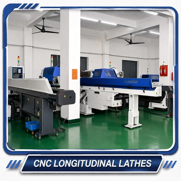
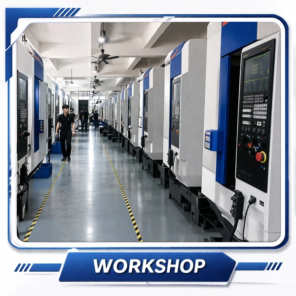
Manufacturing Facility
 |
 |
 |
 |
Site Classification Matrix — Select the Right Worm Shaft Material for Your Installation
Material selection for the worm shaft should be driven by the corrosive severity of the site atmosphere, not by the lowest available price at a given module. This matrix covers the four site types most frequently encountered in Korean and Asian solar projects:
| Site Type | คำอธิบาย | Recommended Worm Shaft | Corrosion Test Minimum |
|---|---|---|---|
| Inland — Arid or Agricultural | Inland Korea, central/western China, Middle East desert — no significant chloride or industrial air pollution | C45 + zinc phosphate + synthetic grease | 96-hour neutral salt spray per ISO 9227 |
| Inland — Industrial Atmosphere | Industrial park sites, proximity to cement / steel / chemical plants — elevated SO2 or particulate contamination | C45 + hot-dip galvanized (85 µm) or SS304 | 240-hour salt spray; SO2 atmosphere test |
| Coastal — Within 5 km of Sea | West and south coast Korea, Yellow Sea coastline, coastal Southeast Asia — marine chloride atmosphere | SS316 — chloride pitting resistance required | 500-hour salt spray; passivation certificate |
| Floating Solar — Freshwater Reservoir | Reservoir, lake, or large river installations — high humidity, freshwater mist, no chloride | SS304 + IP67 sealed housing — freshwater corrosion only | 96-hour salt spray; IP67 immersion test on housing assembly |
The Duplex Worm Strategy for 25-Year Tracking Accuracy
เอ เฟืองตัวหนอนคู่ set — also called a dual-lead worm — maintains tracking accuracy over the full project lifecycle by allowing backlash to be restored without replacing the gear set. The mechanism works as follows: the worm thread flanks are manufactured with slightly different lead values on the left and right sides, making the thread tooth thickness increase continuously from one end of the worm to the other. Shifting the worm axially by a calibrated amount moves a thicker section of thread into mesh with the wheel, closing the backlash gap. The contact geometry between worm and wheel is unchanged by this shift — the full tooth contact area, load capacity, and self-locking margin remain intact throughout the adjustment. Only the backlash dimension changes.
For a typical solar tracker M6 worm at 80:1 ratio, the lead difference between the two flanks is approximately 0.15 mm per revolution. This gives an adjustment range of approximately 1.0 mm of axial worm shift, corresponding to a backlash adjustment from zero to 0.15 mm at the pitch circle. Backlash accumulates at approximately 0.015–0.025 mm per year in normal tracker operation. Starting from 0.05 mm at installation, the drive reaches the 0.10 mm adjustment threshold in approximately 2 to 4 years. An O&M team performing the axial shift adjustment at this interval — a 20-minute procedure with standard hand tools — restores the drive to 0.05 mm backlash. The procedure can be repeated 4 to 6 times before the wheel teeth wear to the replacement limit, giving a total service life of 10 to 25 years without component replacement depending on contact stress level and lubrication quality. For a project that financed on a 25-year lifespan, this is the worm gear strategy that matches the business model.
Tracker System Compatibility Reference
Brand names are listed for dimensional reference purposes only. Korea Ever-Power is not affiliated with, endorsed by, or authorized by any tracker manufacturer listed. All trademarks are the property of their respective owners.
| Tracker System | Drive Type | Matching Notes |
|---|---|---|
| NEXTracker (NX Horizon) | Slew drive with internal worm gear | Module and tooth count confirmation required — send internal drive dimensions |
| Array Technologies (ATI) | Gear reduction drive with worm stage | Dimensional drawing required for matching |
| PVHardware | Dedicated tracker slew drive units | Module M5–M8 — send part number for quotation |
| GameChange Solar | Motor-integrated worm drive | Custom bore and motor flange matching available |
| Ideematec | Slew ring and worm drive combination | Module and center distance confirmation needed |
Project Reference Cases
EPC Contractor — South Jeolla Coastal Project, South Korea · Q2 2023
ขับ: Single-axis horizontal tracker, 28 MW, 4.2 km from Yellow Sea coast. M6, 80:1, SS316 worm shaft, tin bronze wheel, 500-hour salt spray tested
The EPC contractor had experienced corrosion-induced drive failures on a previous coastal project where zinc-plated C45 shafts developed through-wall pits within 4 years. The new project owner required documented 25-year corrosion resistance evidence — a statement on a datasheet was not acceptable. SS316 worm shafts electropolished to Ra 0.4 µm were specified. 500-hour neutral salt spray test confirmed no base metal corrosion on tooth surfaces. Self-locking margin verified at -10°C and +75°C. Three-year field inspection in 2026 confirmed no measurable corrosion on tooth surfaces, backlash within original specification on 95% of units inspected. Second coastal project of 45 MW ordered Q4 2025 using the same specification.
“The 500-hour salt spray result and the temperature-verified self-locking calculation were exactly what the project owner’s technical review needed to approve the specification.” — Project Engineering Director
Tracker Manufacturer — Queensland Dual-Axis Project, Australia · Q1 2024
ขับ: Dual-axis azimuth drive, 150 MW, ambient -5°C to +45°C, maximum housing temperature +85°C. M7 duplex worm, DIN7
The previous standard worm set on the azimuth axis accumulated 0.6 degrees of backlash within 6 years, triggering a mid-project re-specification requirement. The tracker manufacturer required a duplex solution that maintained tracking accuracy within ±0.3 degrees over 25 years without gear set replacement. Duplex M7 adjusted to 0.06 mm at installation; lead difference of 0.18 mm/rev provides an 0.8 mm adjustment range. Synthetic PAO NLGI 2 grease rated to 140°C specified for Queensland summer housing temperatures. 12-month inspection: backlash measured at 0.09 mm — within 0.10 mm threshold, no adjustment required at this interval.
“The duplex adjustment guide was in the packaging. My O&M team used it directly in the maintenance protocol documentation for the 25-year O&M contract.”
Desert Solar Project — Saudi Arabia, 500 MW · Q3 2023
ขับ: Single-axis horizontal tracker azimuth drives, desert environment, ambient -5°C to +50°C, housing temperature to +85°C. C45 + hot-dip galvanizing 85 µm, 720-hour salt spray tested
Previous tracker drives used mineral grease that showed oil separation at housing temperatures above 75°C during summer peak generation hours — leaving the worm mesh running on dry thickener for 3 to 4 hours daily. Specified synthetic PAO NLGI 2 calcium sulfonate grease rated from -40°C to +140°C. At the 24-month inspection: grease sample viscosity within specification and no thermal degradation products detected by ferrography. Zero lubrication-related failures across the fleet in the period.
“Two years with zero lubrication failures in a 500 MW fleet in a desert climate. The synthetic grease specification was the correct solution.”
Floating Solar Project — Mekong Delta, Vietnam · Q4 2024
ขับ: Azimuth drive, 45 MW floating array on reservoir. High relative humidity, freshwater mist, tropical temperature 15–42°C ambient. SS304 worm shaft, IP67 sealed housing
Previous supplier’s carbon steel shafts with standard zinc plating delaminated at bearing support areas within 18 months due to condensation cycling and freshwater mineral deposits. SS304 was specified — sufficient corrosion resistance in freshwater without the cost premium of SS316. IP67 sealed bearing housing journals prevented condensation ingress at the most vulnerable shaft location. 14-month inspection: no corrosion on shaft surfaces, all seals intact. Second 30 MW floating project commissioned early 2025 using identical specification.
“SS304 instead of SS316 saved meaningful cost without compromising durability in a freshwater environment. The recommendation was technically correct.”
Standard Catalog Spec vs 25-Year Solar Tracker Specification
| ปัจจัย | Standard Catalog Worm Gear | Korea Ever-Power 25-Year Solar Spec |
|---|---|---|
| Shaft material (coastal) | C45 + zinc plating — pits through in 5–7 years coastal atmosphere | SS316 — molybdenum suppresses chloride pitting for full 25-year project life |
| Self-locking verification | Stated on datasheet at ambient temperature only | Calculated and documented at site temperature extremes — safety margin traceable |
| Backlash at year 10+ | 0.15–0.20 mm — tracking accuracy degraded, energy yield loss | Duplex: restored to 0.05 mm at each O&M adjustment interval — accuracy maintained |
| ข้อกำหนดของสารหล่อลื่น | Mineral NLGI 2 — oil separation above 75°C, dry tooth surfaces in summer peak | Synthetic PAO NLGI 2, 140°C rated — no bleed at any site operating temperature |
| Project documentation | Product datasheet | Material cert, salt spray test, self-locking calculation, fatigue life calculation, lubricant compatibility statement |
| Expected unplanned maintenance | 1–3 gearbox replacement events in 25 years | Zero unplanned — scheduled backlash adjustments every 2–4 years only |

สำหรับงานที่ต้องการชุดขับเคลื่อนแบบหมุนครบชุด พร้อมวัสดุและเอกสารประกอบตามที่ระบุไว้ในคู่มือนี้ มีชุดเฟืองตัวหนอนแบบจับคู่ที่ประกอบเสร็จแล้วพร้อมจำหน่ายในตัวเรือนปิดผนึก IP67 สำหรับการติดตั้งบนท่อแรงบิดมาตรฐาน ตัวเรือนขนาดกะทัดรัดแบบปิดมิดชิด เกียร์ทดรอบแบบหนอน โดยสามารถเลือกวัสดุที่เหมาะสมกับพื้นที่ได้ ไม่ว่าจะเป็นบนบก ชายฝั่ง หรือลอยน้ำ มีให้เลือกเป็นชุดพร้อมติดตั้งครบถ้วน เอกสารประกอบการประเมินคุณสมบัติโครงการอย่างครบถ้วนจะถูกจัดเตรียมไว้เป็นมาตรฐานสำหรับการตรวจสอบโดยฝ่ายวิศวกรรม การจัดซื้อ และการบริหารจัดการสินทรัพย์
คำถามที่พบบ่อย
ระบุรุ่นของชุดขับเคลื่อนเฟืองตัวหนอนสำหรับระบบติดตามแสงอาทิตย์ของคุณ — รวมเอกสารโครงการฉบับสมบูรณ์แล้ว
ส่งพารามิเตอร์ของระบบขับเคลื่อนติดตามของคุณ: โมดูล อัตราส่วน แรงบิดเอาต์พุต ตำแหน่งติดตั้ง และระดับสภาพแวดล้อม ช่วงอุณหภูมิ และข้อกำหนดด้านเอกสาร เราจะตอบกลับพร้อมข้อมูลจำเพาะที่ได้รับการยืนยัน ขอบเขตของแพ็คเกจการตรวจสอบคุณสมบัติ และราคาภายในหนึ่งวันทำการ มีข้อตกลงรักษาความลับ (NDA) ก่อนการแลกเปลี่ยนแบบร่าง
บรรณาธิการ: Cxm