圆柱形蜗轮 | 线接触,高负载能力,青铜和铸铁

Cylindrical worm wheels with arc-curved tooth face for true line contact meshing — load capacity 3–5× higher than crossed helical gear point-contact alternatives at the same module. Available in cast tin bronze (ZCuSn10Pb1), aluminum-iron bronze, grey cast iron, and ductile iron. Suited for industrial conveyors, hoists, CNC rotary tables, solar trackers, and agricultural gearboxes running at continuous duty. Precision from DIN6 to DIN9. Custom tooth count and center distance on request.
产品概述
Two configurations are both called "cylindrical worm wheel," yet only one is capable of handling sustained industrial loads. The difference is not visible to the eye and cannot be determined from the tooth count, module, or material alone. It comes down to the tool used to cut the wheel teeth: a standard helical gear hob cuts a wheel with straight-profile teeth that produce only point contact when meshed with a cylindrical worm. A worm-profile hob — whose cutting edge geometry matches the worm thread form — mills an arc-curved tooth face on the wheel that envelops part of the worm circumference, converting the contact geometry from a point to a line. This line contact spans a significant fraction of the tooth face width and raises the admissible load by a factor of 3 to 5 at the same module. Korea Ever-Power Worm Gear Co., Ltd manufactures cylindrical worm wheels using the correct worm-profile hob for each module, producing true line-contact wheels for industrial, agricultural, and precision positioning applications.

The Two Types of Cylindrical Worm Drive — What Engineers Must Know
The confusion between the two types arises because both use a cylindrical (as opposed to globoidal or hourglass-shaped) worm. That is where the similarity ends. Understanding the distinction prevents selecting an undersized drive for a continuous-duty application.
Type A — Worm + Helical Gear (Point Contact)
The first type is a special case of helical gears for crossed shafts. The "worm" in this arrangement is simply a helical pinion with 1, 2, or 3 teeth and a very large helix angle. The paired helical gear is a standard involute helical gear cut with a conventional hob. The calculation follows helical gear methodology — the module must be selected from the normalized standard module series. Only theoretical point contact exists between the mating tooth flanks at any instant. Under load, this contact expands to a small ellipse, but the contact area remains a small fraction of the tooth face width. This severely limits the load capacity: even at the same module and material, a point-contact worm set handles roughly 20–30% of the load a line-contact pair can sustain.
Suitable for: Instrument drives, low-speed light motion, shaft angle conversion at low torque. Not suitable for sustained high loads or continuous industrial duty.
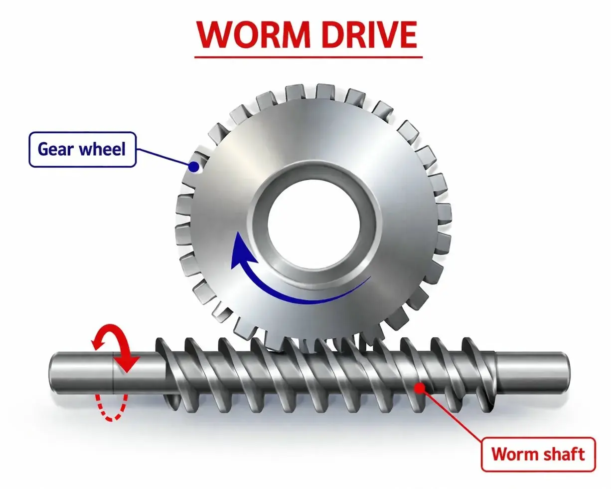
Type B — Worm + Worm Wheel (Line Contact) — This Product
In the true worm-and-wheel arrangement, the wheel teeth are milled with a hob that replicates the worm thread profile. The hob geometry causes the wheel tooth face to curve along the tooth width direction in an arc that matches the worm's pitch cylinder. When assembled at the correct center distance, this arc-curved face partially wraps around the worm — the contact zone spans a line rather than a point. This line contact geometry distributes the applied load over a much larger area, allowing the same module and material to sustain 3–5× more load than the point-contact Type A arrangement. All worm wheels from Korea Ever-Power are Type B, cut with the correct worm-profile hob for each module and lead angle.
Suitable for: Power transmission at moderate to high continuous loads — conveyors, hoists, agricultural gearboxes, CNC auxiliary drives, solar trackers, general industrial machinery.
Line Contact vs Point Contact — Side-by-Side Comparison
This comparison is written for engineers deciding between the two drive types at the specification stage. The numbers in the load capacity and contact area rows are approximate; your specific module, material, and operating conditions determine the exact values. Contact us with your torque and speed requirement for a sizing calculation.
| Engineering Factor | Type A — Worm + Helical Gear (Point Contact) |
Type B — Worm + Worm Wheel (Line Contact) — This Product |
|---|---|---|
| Tooth contact geometry | Theoretical point — small ellipse under load (≈2–8 mm²) | Line across tooth face width — contact zone (≈15–40 mm² at M5) |
| Continuous torque capacity | Low — suited to light-duty motion and instrument drives only | 3–5× higher than Type A at same module and material |
| Wheel tooth cutting tool | Standard helical gear hob — widely available, lower tooling cost | Worm-profile hob matched to worm geometry — higher tooling cost, correct form mandatory |
| Ratio range practical | 3:1 to 15:1 — large ratios require many teeth on the helical pinion, making it impractical | 5:1 to 300:1 in a single stage — the standard worm drive ratio range |
| Module standard | Must use normalized standard module series — no interpolated values | Standard modules — worm and wheel hob are matched to same module |
| Lubrication requirement | Light lubrication often adequate at small point-contact loads | Oil film lubrication essential at medium-to-high loads — correct viscosity grade critical |
| Bronze wheel requirement | Not required — steel helical gears acceptable at light loads | Bronze or cast iron wheel strongly recommended to manage sliding wear at the mesh |
| Recommended application | Instrument motion, light-load shaft angle conversion, low-duty positioning | Industrial power transmission, continuous duty machinery, precision rotary drives |
Material Selection for Line-Contact Worm Wheels
Material choice determines two things simultaneously: how much load the wheel can sustain before tooth surface fatigue, and how long it takes to reach that failure. The tribological mechanism at a worm mesh — high sliding velocity, significant thermal load — eliminates most metals from practical consideration and points to a short list of alloys that have been validated by decades of industrial service.
Cast Tin Bronze (ZCuSn10Pb1)
The canonical worm wheel material for continuous-duty applications against a hardened steel worm. Tin content (10%) provides good anti-friction properties and creates a protective oxide layer at the tooth surface during running-in that reduces the effective friction coefficient to approximately 0.05–0.10 with oil lubrication. Lead content (1%) improves machinability without significantly reducing strength. Tensile strength approximately 250–290 MPa — lower than steel or aluminum bronze but adequate for worm wheel applications where compressive surface stress, not tensile fracture, is the governing failure mode. The primary limitation: sulfur and chlorine-based extreme-pressure (EP) oil additives chemically attack the tin content and accelerate corrosive wear — specify mineral oil or PTFE-based lubricants without EP additives.
Best for: Continuous duty, high sliding speeds, applications where anti-galling performance is the top priority.
Aluminum-Iron Bronze (ZCuAl10Fe3)
Higher tensile strength (550–600 MPa) than tin bronze, making it the correct choice for heavily loaded intermittent applications where the tooth root bending stress is a concern alongside surface wear. The aluminum content provides moderate anti-galling properties — better than steel on steel, but somewhat weaker than tin bronze under continuous high-speed sliding. Price per kilogram is lower than tin bronze. Compatible with most industrial gear oil formulations including moderate EP additives. The tradeoff versus tin bronze is measurable: at the same module and load, aluminum bronze worm wheels show approximately 20–30% higher wear rate in continuous sliding tests — acceptable for intermittent or seasonal operation, less suitable for 24/7 continuous drives.
Best for: Heavy intermittent loads, seasonal machinery, applications where cost is a significant constraint and continuous duty is not required.
Grey Cast Iron / Ductile Iron
The lowest-cost worm wheel material, appropriate for slow drives (pitch line velocity below 2 m/s) and non-critical applications. Grey iron contains graphite flakes that act as a solid lubricant during the initial mesh contact — providing moderate anti-galling behavior without oil in very short-duty situations. Ductile (nodular) iron has significantly better impact resistance than grey iron, making it preferable for machinery subject to shock loading (stone crushers, agricultural equipment hitting rocks). Both grades require aging treatment after casting to stabilize dimensions and prevent warping during machining — unskipped aging is the most common cause of bore and tooth concentricity problems in cast iron wheels. Grey and ductile iron are compatible with EP oil additives, unlike bronze grades.
Best for: Low-speed, non-critical drives; budget-sensitive applications; machinery requiring shock load resistance (ductile iron).
Lubrication System Design — Oil Splash Ring and Overhead Worm Arrangement
Worm gearbox lubrication design has two failure modes that are less common in parallel-axis gear drives: insufficient oil reaching the worm mesh, and excessive oil reaching the worm bearing. Both cause accelerated wear or overheating. Two specific solutions address these problems:
Oil splash ring when worm is submerged but wheel is not: When the oil sump level is set correctly for the worm bearing (preventing deep immersion that causes viscous churning losses), the worm itself may not be sufficiently immersed to splash oil to the mesh zone. An oil splash ring — a disc or ring fitted on the worm shaft — rotates with the worm, dips into the sump oil, and throws oil upward toward the mesh and worm wheel. This simple component solves the oil distribution problem without increasing the sump level and without using forced circulation pumps. Splash rings are particularly important in horizontal-shaft gearboxes where the worm is above the oil level by design.
Overhead worm arrangement when pitch line velocity exceeds 10 m/s: When the worm pitch line velocity is high (above approximately 10 m/s), the centrifugal and pumping effects of the worm thread become significant. In a standard "bottom worm" arrangement at these speeds, the worm churns through the oil sump at high velocity, generating foam, raising oil temperature, and increasing viscous losses. The solution is an overhead arrangement — the worm is positioned above the worm wheel, and the wheel dips into the oil sump instead. The wheel's peripheral velocity is much lower than the worm's for any given ratio (lower by the ratio factor), so churning losses are dramatically reduced. Contamination from abrasive particles settling in the sump is also reduced because the particles must travel upward against gravity to reach the mesh zone — the overhead arrangement is inherently cleaner.
Practical guideline: For drives running continuously at output loads above 20% of rated capacity, specify the gearbox housing thermal dissipation area at quotation. A correctly sized housing surface can reject 0.3–0.8 kW/m² of waste heat to still air. If the calculated heat generation exceeds the housing's natural convection capacity, a cooling fan or oil cooler is needed before the oil temperature reaches the lubricant's thermal degradation ceiling.
Applications Where Line-Contact Worm Wheels Are the Correct Choice
- ▶Industrial conveyors and material handling — Head pulley drives on inclined conveyors must sustain continuous high-torque operation while the self-locking property prevents the belt from running backwards when the motor stops. Bronze worm wheels in these applications are chosen for their anti-galling properties under the sustained sliding contact at constant speed. A typical 11 kW conveyor drive at 30:1 reduction runs the worm wheel tooth face through thousands of sliding cycles per hour — tin bronze sustains this where grey iron would gall within weeks.
- ▶CNC 4th-axis rotary tables and tilting heads — Precision rotary table drives use worm and worm wheel as the final reduction stage for angular positioning. The angular positioning accuracy directly depends on the pitch error and lead error of the worm wheel teeth. A DIN6 bronze worm wheel at M5 with 60 teeth produces approximately ±8–12 arc-seconds of single-tooth indexing accuracy — acceptable for most machining center 4th-axis applications where the requirement is typically ±30 arc-seconds. Higher precision requires a DIN5 class or a master-lapped pair tested on a rotary table tester.
- ▶Agricultural machinery gearboxes — Rotary tillers, transplanting machines, and irrigation pumps use worm and wheel drives in wet, dirty, vibration-heavy field conditions. Aluminum-iron bronze is often preferred over tin bronze here because the higher tensile strength (550 MPa vs 270 MPa) provides better resistance to the impact loads from hitting stones and root obstructions in the soil. The drive may also sit unmaintained for months between seasons — a worm drive's sealed gearbox retains lubricant better than chain or belt alternatives.
- ▶Manual and electric hoists — Load-holding without power is a safety requirement for overhead material handling. Worm drives at ratios of 15:1 and above reliably self-lock under static load when the lead angle is below the friction angle. The worm wheel material must sustain repeated tooth loading from start-stop cycles under full rated load — tin bronze's superior creep resistance at sustained surface pressure makes it the appropriate wheel material for hoist applications versus grey iron, which creeps (permanently deforms) under sustained high surface pressure.
- ▶Solar panel tracking drives — Single-axis and dual-axis solar trackers require slow, continuous rotation (approximately 0.25 RPM for daily east-west tracking) with the drive holding position against wind loading between movements. High reduction ratios (60:1 to 150:1) in a compact sealed gearbox suit the application. The self-locking property resists wind gusts without additional braking hardware. Bronze worm wheels in outdoor tracker drives typically last 15–25 years — consistent with the 25-year design life of commercial solar installations.
- ▶Parking systems and automated storage — Automated multi-level car parking and vertical carousel storage systems use worm drives for the lift and transfer mechanisms. The requirement is a combination of moderate speed, high reliability, and fail-safe position holding if power is lost — all conditions worm-and-wheel drives satisfy naturally. Ductile iron worm wheels are specified in some parking system drives where impact load (vehicles not perfectly centered) and long service life between inspections are both priorities.

Manufacturing Capability
Production equipment includes NC gear hobbing machines, NC gear shapers (Gleason, Mode), NC lathes, NC gear shaving machines, NC gear milling machines, and NC gear grinding machines. Quality control instruments include gear-profile CMM measurement and rolled-mesh testing on matched worm and wheel pairs. All raw bronze and iron materials are verified against supplier certificates before entering production.
 |
 |
 |
 |
 |
 |
相关组件
Matched hardened steel worm shafts and sealed gearbox housings in the same module and center distance are available alongside the bare worm wheel. For complete enclosed drives, compact 蜗轮减速器 with tested matched sets are stocked and made-to-order. The full component catalog covers both bare gear sets and complete gearboxes from the same manufacturing source.

常见问题解答
How do I verify that the wheel I receive is line-contact Type B and not a helical gear incorrectly described as a worm wheel?
The clearest visual check is the tooth face curvature across the width. On a Type B worm wheel, the tooth face is concave across the face width — the center of the tooth dips inward compared to the edges when viewed from above the tooth tip. On a Type A helical gear, the tooth face is straight across the width (or slightly convex on crowned gears). A more reliable check is the rolled contact test: mesh the wheel with its paired worm at the correct center distance and roll it under light load with marking compound on the worm thread. A Type B wheel shows a contact pattern stretching across a significant fraction of the tooth width. A Type A gear shows a small diagonal spot contact near the tooth center. All Korea Ever-Power worm wheels are Type B and are mesh-tested with the matched worm before shipment.
Can I use an EP gear oil with a bronze worm wheel?
It depends on the EP additive type. Sulfur-phosphorus EP additives (the most common type in industrial gear oils labeled "EP") react chemically with the copper and tin in bronze alloys, forming copper sulfides that corrode the tooth surface. This corrosive wear can be 3–5× faster than normal sliding wear under the same load and speed conditions — and it is often misidentified as mechanical overload because the tooth surface appearance can be similar. To use EP-grade oil with bronze wheels, specify an EP oil formulated with ashless or non-sulfur EP additives — these are available from major lubricant manufacturers specifically for bronze-gear applications. When in doubt, use an ISO VG 220 or VG 460 mineral oil without EP additives in bronze worm drives.
What software do you use for product drawings and custom design?
We use AutoCAD and SolidWorks for 2D and 3D design work. Customer drawings are accepted in DWG, DXF, STEP, IGES, or SolidWorks native format. For custom worm wheel designs where only the mating worm geometry is available, we extract the worm parameters (module, lead angle, thread form, center distance) and generate the wheel drawing from those specifications. The confirmed wheel drawing is returned for customer approval before production begins.
How does your factory control quality at each production step?
Quality control operates at three checkpoints: incoming material inspection (chemical composition and hardness verified against supplier mill certificates), in-process dimensional check after hobbing (tooth profile on CMM, bore diameter and concentricity with gauge), and final inspection before packing (complete dimensional check on a sample from each batch, mesh test on matched pairs). The quality control department is independent of the production department and has authority to hold batches failing any inspection criterion. Inspection records are retained and can be provided with shipment on request.
How do I handle an equipment failure during service?
Email us a description of the failure with photographs or video — visual evidence is the most efficient way to identify the failure mode. Common failure modes in worm drives each have a distinct visual signature: abrasive wear (smooth, polished tooth face with material loss), adhesive wear/galling (torn or pitted surface with material transfer), fatigue pitting (small craters on the tooth face in the contact zone), and corrosive wear (rough, etched surface, often with discoloration). We will advise on the cause and corrective action. If the failure is within warranty and confirmed as a manufacturing defect, we send replacement parts at no charge.
What is your intellectual property protection policy?
Korea Ever-Power implements strict IPR protection policies for all OEM customers. Customer design drawings, 3D models, tooling specifications, logo files, and artwork are not released to any third party without written permission from the customer. We can sign a Non-Disclosure Agreement (NDA) before any drawing or sample is submitted — this is our standard process for new OEM relationships, not an exception. Production tooling made to customer specifications is held as dedicated tooling and not used for any other customer's production.
用户评价
Jung Min-soo — CNC Application Engineer, Seoul Precision Machines Co. (Q2 2026)
Needed DIN7 class M5 tin bronze worm wheels for a rotary table retrofit on a five-axis machining center. Incoming measurement on our CMM confirmed all three sample pieces within DIN7 tolerance on tooth pitch, lead, and bore concentricity. After installation and warm-up, angular repeatability improved from ±22 arc-seconds to ±11 arc-seconds — a meaningful improvement for our customers' contour milling operations. Korea Ever-Power supplied the matched worm shaft in the same order with mesh test data attached. The worm and wheel meshed correctly at our nominal center distance without any shimming.
Song Hye-jin — Maintenance Manager, Gyeonggi Agricultural Equipment (Q3 2025)
Replaced aluminum-iron bronze worm wheels on 12 rotary tiller gearboxes ahead of the autumn season. All 12 bore diameters measured within H8 tolerance on incoming — no reaming, straight to assembly. After a full growing season of field operation with daily use in wet conditions and occasional stone impacts, tooth wear is visually minimal on all units. We sent photos at the six-month mark and Korea Ever-Power confirmed the wear pattern is normal running-in wear, not accelerated failure. Unit price was 20% below our previous Taiwanese supplier for equivalent quality at equivalent minimum order quantity.
Kwon Jae-sung — Chief Engineer, Incheon Industrial Hoist Co. (Late 2025)
Self-locking is a safety-critical requirement for our 2-ton manual chain hoist. We specified tin bronze worm wheels — not the cheaper grey iron alternative — because creep under sustained high surface pressure is a failure mode we cannot accept on overhead lifting equipment. Korea Ever-Power supplied the material test certificate with the batch and engaged with our lead angle verification calculation. Eight months of daily operation under rated load with no measurable increase in static backlash. Our periodic safety inspection found no tooth surface anomalies. The price premium over grey iron was 22% — fully justified for the application.
Lim Sung-ho — Production Buyer, Busan Conveyor Solutions (Q1 2026)
We purchase M4 and M6 tin bronze worm wheels quarterly for conveyor drive rebuilds. The batch-to-batch consistency that matters most to us is bore diameter and tooth pitch — our rebuild techs work to a standard procedure and any variation means extra fitting time. Six quarters of sourcing from Korea Ever-Power: bore diameter spread within ±0.010 mm batch-to-batch, tooth pitch error within DIN8 on all batches measured. Lead time consistently 22–24 days. No surprises, no late deliveries, no quality holds. That is exactly what a maintenance parts supplier should deliver.
包装与运输
Inner packing: individual oil-paper wrap and polyethylene bag for each wheel. Outer packing: wooden case or carton depending on quantity and weight. Payment: T/T, L/C before shipment. Lead time: 20 business days for samples, 25 days for production quantities. Custom packing for OEM customers accepted.

附加信息
| 编辑 | CXM |
|---|


